Hardware specs
- Custom PCB and 3D-printed case
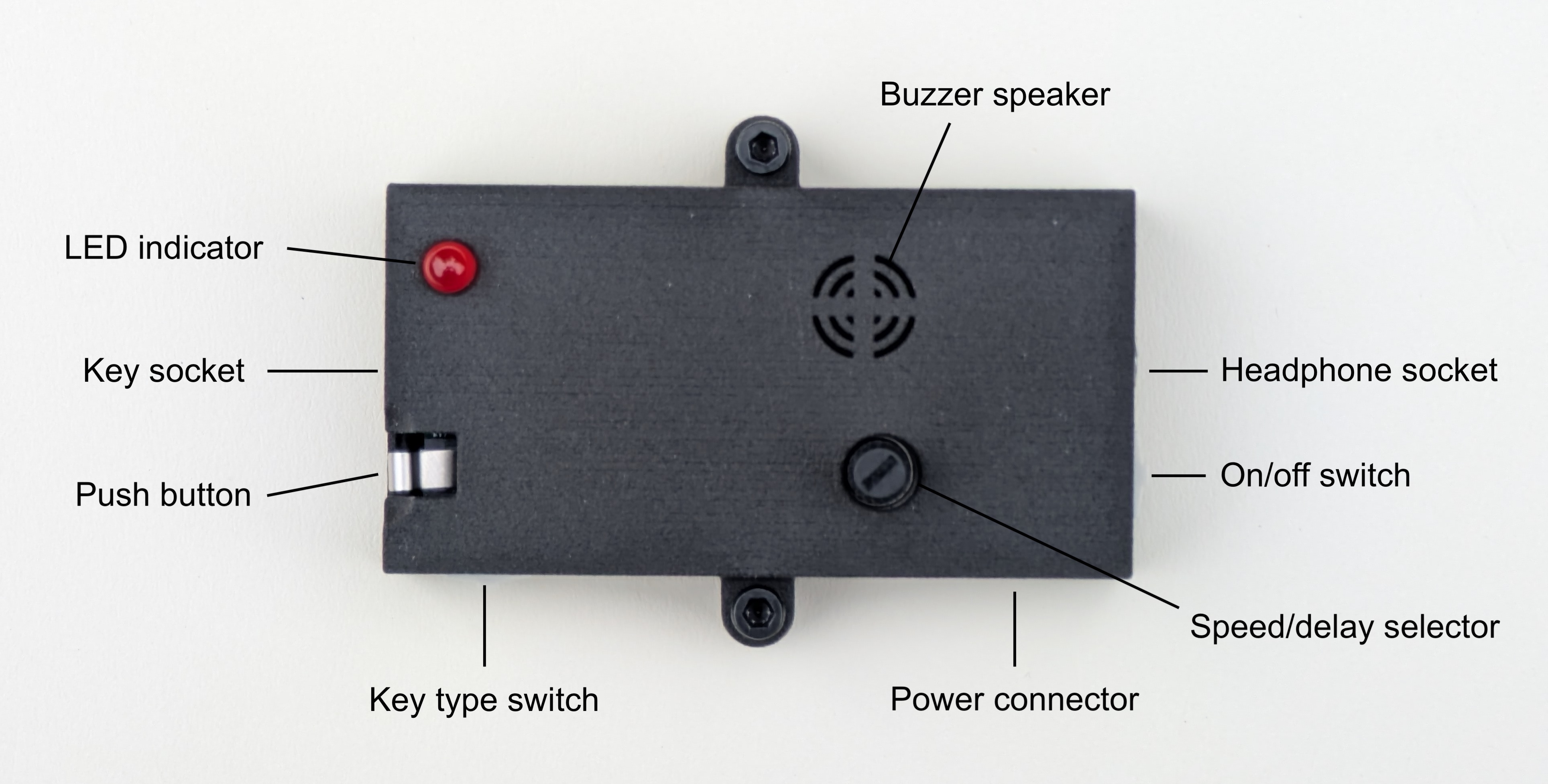
- 3.5mm socket for paddle or straight key
- 3.5mm socket for headphones
- Built-in buzzer speaker, automatically disabled when headphones are used
- Speed selector with physical dial
- Visual indicator LED
- On-board push switch for straight key practice and triggering practice words
- 4-5 volt JST-PH power connector
Dimensions
- Case without protrusions: 7.2 x 3.7 x 1.8 cm (2.83 x 1.46 x 0.71 in)
- Case with all protrusions (screw mounts, switches, dials): 7.4 x 5.1 x 2.6 cm (2.91 x 2.01 x 1.02 in)
- Weight: 37 g (1.31 oz)
- Weight with battery pack: 91 g (3.21 oz)
Operating your KeyerBuddy
Power on your KeyerBuddy
Connect the 3xAAA battery pack to the KeyerBuddy power socket on the side of the enclosure. Keep in mind that the battery pack has a dedicated on-off switch, and the KeyerBuddy also has an on-off switch. Both of these need to be set to 'on'. When powering on, your KeyerBuddy will beep twice.
KeyerBuddy can be powered with 4.5-5 volts, so a USB->JST-PH 2-pin 2mm adapter cable can also be used.
Connect your key
Connect your paddle or straight key to the key socket on your KeyerBuddy using a 3.5mm TRS cable.
Use headphones
Connect your headphones to the audio socket on your KeyerBuddy.
If no headphones are plugged in, the built-in buzzer speaker will be used. When headphones are plugged in, the buzzer speaker will be muted.
Set the speed/delay
The keying and sending speed/delay is set using the thin round dial on the front. Turning the dial clockwise lowers the speed (increases the delay), and vice versa. This speed is used for paddle keying, as well as when KeyerBuddy sends messages for copying practice.
Key type selection
The key type slider switch (next to the push switch) selects which keying mode to use: paddle or straight. Use this switch to select the right key type for the key you have plugged in.
On-board push switch
The on-board push switch protrudes through the top edge of the enclosure. Its function depends on the key type and whether or not a key is plugged in. The simple rule is:
- If the key type is set to straight, and no key is plugged into the key socket, then the push switch behaves as a straight key. It will produce a tone as long as it is pressed down.
- In all other configurations, the push switch is used to trigger the KeyerBuddy to send a word for copying practice.
Practice copying
When using your KeyerBuddy to practice copying, you can listen to two different kinds of transmissions:
- Press and release the push button quickly: listen to a randomly selected word from the built-in dictionary containing 100 commonly used CW abbreviations and phrases.
- Press and hold the push button: listen to a randomly generated callsign in the format LLNLLL. Bonus: 10% of the time you will get a /P callsign.
Assembly instructions
KeyerBuddy is simple to assemble with through-the-hole components, making for a fun soldering project.
Tips when assembling and soldering your KeyerBuddy
- The J2 2x3 pin header is optional and is used for programming the microcontroller. The included microcontroller IC has been preprogrammed, so this is an optional component. I would recommend adding it while you're at it, but it's not necessary.
- Make sure components sit flush against the PCB. If you are having trouble with this, try soldering one pin of the component first. If you end up with a gap you can easily reheat the solder and reposition the component. When you're satisfied with its placement, solder the remaining pins.
- Mount resistors and diodes last.
- Use the provided DIL-20 socket for the microcontroller IC – do NOT solder the IC straight to the board, because this makes it impossible to swap later for a firmware upgrade or spare.
- You will need to adjust the angle of the microcontroller IC's pins to make them fit into the DIL-20 socket. This is best done by pressing all pins against a flat surface. Make sure to not overbend – only bend each side a little, check the fit, and if necessary repeat the process.
- Make sure to solder the reverse polarity protection diode D2 in the correct direction.
Tips when using the 3D-printed enclosure
- Make sure to continuously check the fit. Remember that the enclosure provides approx. 2mm of clearance below the PCB, so you need to trim some of the leads to <2mm below the PCB after soldering them in.
- I recommend soldering the audio sockets first, because they should sit flush, do not need to be trimmed, and are important components to ensure the PCB fit into the enclosure. Make sure the lid fits snug around the sockets. Start by soldering only one pin, check the fit, and then solder the rest if the fit is good.
- The sliding switches need to protrude through their matching holes in the enclosure. The best fit is achieved when the pins are bent a full 90 degrees immediately out of the switch component (as provided in the kit), and the side of the switch is then sitting snugly against the PCB. Try not to leave any gap between the switch and the PCB.
- Be careful when mounting the LED – it is the only component that should not sit flush with the PCB, because it needs to protrude through the hole in the lid of the enclosure. The distance to the PCB will vary depending on how much you want it to protrude.
- Make sure the white 2-pin power connector is pointing out at a right angle – if it's not straight it may not fit the slot in the enclosure. Check the fit early and often, and only solder a single pin to check the fit.
If trouble strikes
If you fudge any component (or find that a component is not functional) and need a new one, just reach out and I'll gladly ship you a replacement.
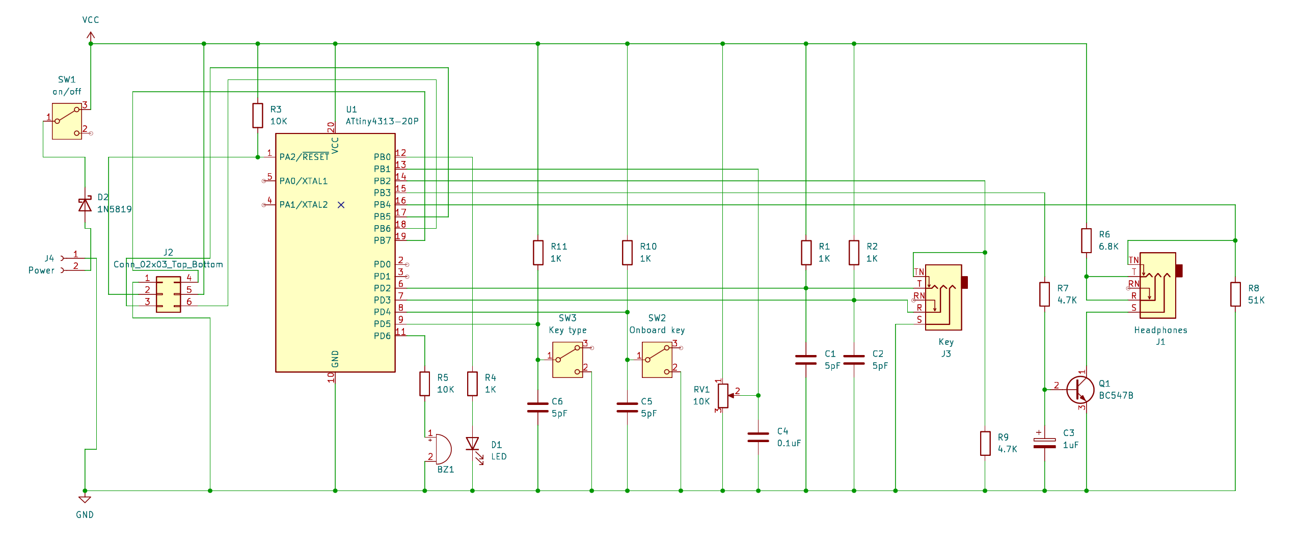
PCB bill of materials
Revision 3.1
| Reference | Qty | Value |
|---|---|---|
| BZ1 | 1 | Buzzer |
| C1,C2,C5,C6 | 4 | 5pF |
| C3 | 1 | 1uF |
| C4 | 1 | 0.1uF (100nF) |
| D1 | 1 | LED |
| J1 | 1 | 3.5mm headphone socket |
| J2 | 1 | Programmer pins 2x3 |
| J3 | 1 | 3.5mm key socket |
| J4 | 1 | 2-pin power connector |
| Q1 | 1 | BC547B |
| R1,R2,R4,R10,R11 | 5 | 1K |
| R3,R5 | 2 | 10K |
| R6 | 1 | 6.8K |
| R7,R9 | 2 | 4.7K |
| R8 | 1 | 51K |
| RV1 | 1 | 10K |
| SW1 | 1 | On/off slider switch |
| SW3 | 1 | Key type slider switch |
| SW2 | 1 | Onboard push key microswitch |
| U1 | 1 | ATtiny4313-20P |
| U1 socket | 1 | DIL-20 |
| D2 | 1 | 1N5819 |